Installation
Mounting
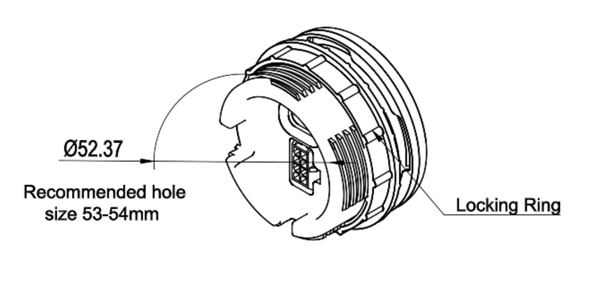
The display fits a round hole and is held from behind by its locking ring.
- Drill or cut a 53–54 mm hole. The body is Ø 52.37 mm.
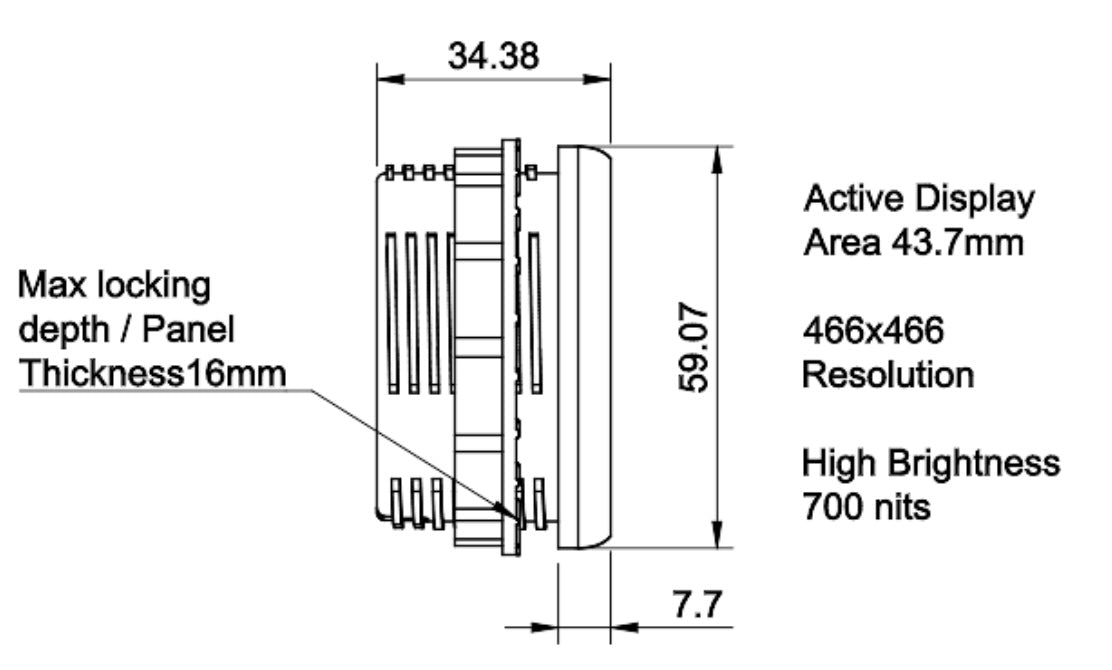
- Push the display in from the front. The panel can be up to 16 mm thick.
- Screw the locking ring on from behind until the display is held firmly.
Leave about 27 mm behind the panel for the display, plus room for the plug and its wires.
Connector and pinout
On the back are the 8-pin connector and the USB-C port.
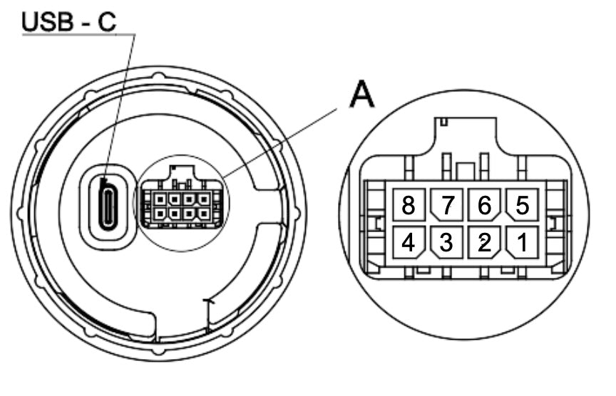
| Pin | Signal | Wire colour | Connect to |
|---|---|---|---|
| 1 | GND | Black | Ground |
| 2 | CAN L | Green | Vehicle CAN low |
| 3 | n/a | TBC | Not used |
| 4 | n/a | TBC | Not used |
| 5 | 12 V | Red | 12 V supply, fused |
| 6 | CAN H | Blue | Vehicle CAN high |
| 7 | Ignition | Pink | Switched 12 V. Optional: only with the "Ignition wire (pin 7)" setting |
| 8 | n/a | TBC | Not used |
The connector is a Molex Micro-Fit 3.0, 2 × 4 pins.
Wiring
- Power: connect 12 V (pin 5) through a fuse, and ground (pin 1). On a permanent 12 V supply the display sleeps when the car is off (10.2 mW) and wakes by itself.
- CAN: connect CAN H and CAN L to the bus that carries the Resolve Controller's and the Leaf parts' messages (500 kbit/s). Twist the pair.
The display has no 120 Ω termination. Connect it as a branch of a bus that is already terminated at both ends: about 60 Ω between CAN H and CAN L, measured with everything off. Keep the branch short.
Ignition: when the display turns on
The Ignition source setting decides what turns the display on and off:
| Setting | The display is on | Pin 7 |
|---|---|---|
| CAN signal (Display on) (default) | while the Display on CAN signal is 1: by default the Resolve Controller is on (ignition on, or charging) | not connected |
| Ignition wire (pin 7) | while pin 7 has 12 V | switched 12 V that is on with the ignition |
With CAN signal the display is also on while the car charges. A charge cable on its own does not turn it on; it only chooses the charging screen. While the settings page is connected over USB, the display stays on.
The Display on signal. By default it is the Resolve Controller's own "system on" flag (message 0x539, bit 16), so with a Resolve Controller there is nothing to set. Another controller, or a car without one, can turn the display on with any CAN flag of its own: set it under General → Display on CAN signal on the settings page, like the other CAN signals (paste the DBC line or fill in the ID and bits). The display is on while the signal is 1 or more, and turns off when it is 0 or its message has stopped for 2 seconds. Reset goes back to the Resolve Controller's flag.
When the display is off and nothing is plugged into USB, it sleeps after 10 seconds. With CAN signal it also waits for the CAN bus to go quiet, and wakes on CAN traffic. With Ignition wire (pin 7) it wakes when pin 7 gets 12 V.
After installing
- Connect the display to the settings page and choose the Mode and the Ignition source.
- For the G-force meter: level it once it is mounted (see Settings).